
![]()
![]()
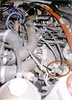
One important point into turbo boosted engines is the inlet air temperature. When the turbine isn't spinning hard enough to actually compress the air, as in any car, the problem reduces itself to the air temperature. On the top of the air filter there is a thermostatic flap that decides where to take the air, cold from the front grille (if air temp is more than 32°C), hot from the exhaust manifold surroundings (if air temp is less than 26°C), or a mixture of both (in between).
There is a cylindrical capsule than controls the flap. It's full of something that heat expands, but with time, it gradually loses efficiency, so that it won't fully close the hot air entry at 32°C. But it's easy to adjust it again.
Fist, take the whole air filter cap home. Put a bucket into your bathtub and fill it with hot and cold water until your medical home thermometer reaches 32°C. Dive the cap into the water, just making sure the capsule is fully into the water, wait for five minutes, and control again the water temperature. Then loose the nut attaching the flap to the rod and tighten it again at the point that the hot air entry (the one with the smaller diameter) is fully closed.
It's interesting to let the car take hot air, in cold weather, but another more radical approach is just to remove the flap and then close the hot air entry, or redirect the hose to make it take cold air too.
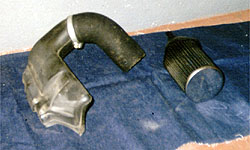
The standard air intake system requires air to pass a restrictive hose and then go through a paper type air filter. In turbo engines that restriction is not that important, because the turbo compressor turbine is itself a bottleneck into the intake section of the engine, but there's a way of reducing the air filter restriction: The bolt-on direct induction kit. It's a cone oil type filter with an elbow that it's fitted directly to the turbo, removing the airbox (Don't confuse with the performance replacement elements that are in the market). It usually includes the input for the crankcase ventilation system hose.
The horsepower gain should be in the 3-7 bhp zone, but the main difference you will notice is a SHHHH sound as soon as turbo starts to blow. It's nice to feel your turbo that way!
The controversy here starts with the point that the air it breaths is all under the bonnet, and that it's located after the intercooler, being hotter than external air. It's true that it's location is not the best, but if you think that whenever the turbo is in operation and the intercooler is getting hot, the car's in movement and there's airflow... And don't forget the standard air filter box is metallic and becomes very hot from being close to the turbo, so heating the air as it passes through it...
|
Buy a bolt-on air filter. I installed the JR kit (blue), but there are other brands, like Pipercross, Green, K&N (Out of U.K. they sell something they call a direct induction kit that's only a replacement filter)... |
|
To improve the cool air entry to the system, you can use up the standard air intake to make a cold air entry. Buy aluminized 70 mm Ø flexible pipe and remove the four rivets that keep the standard hose attached to the cold air intake over the intercooler. Cut a suitable amount of your new pipe (20 cm should be enough, it depends on the capacity of your pipe to expand and bend) and use a worm drive hose clip to mount it in the cold air intake. The photo shows the JR kit and the homemade cold air duct, painted black because of thermical performance (and engine bay appearance :-) ). |
 |
| This type of oil filters last more than the standard paper filter
because it can be cleaned. But if you don't want to get poor airflow
and the following increase of fuel consumption it requires a more frequent
cleaning. They say you can do 10.000 km as the standard filter without
cleaning, but I found the filter to be very clogged with only 7600 km, and
they weren't done in dusty conditions at all! So I would suggest 5000-6000
km cleanings.
The cleaning procedure, as the maker tells, starts by removing the filter and cleaning the bigger particles externally by tapping gently and brushing the external surface (1). Then insert 3/4 of the filter walls into a special soapy cleaning solution (2) to ease the cleaning of the smaller particles, and clean with water (3) from the inner to the outer part of the filter (opposite way of the air). Finally, an special oil uniform coat must be sprayed (4) on the filter. |
 |
When turbo is in operation, compression of inlet air makes it hotter. We want the air to be compressed so that we fill the cylinders volume with more air (and we add more fuel, so we get more powerful explosions) but we don't want the side effect of getting hotter air, so we use the intercooler to cool it using the external air.
Again, there is a thermostatic flap opening a bypass to the intercooler when the air is not hot enough (up to 43°C) or closing it (from 47°C).
 |
The point of the bypass is that, in cold weather, if external air is very
cold (even assuming it comes from heating around the exhaust manifold),
the heat produced by the turbine shouldn't be lost until a reasonable
temp is reached.
But remember how those thermostatic capsules tend to quit its job when they grow old. And now think how air will avoid to go through the difficult long way up the intercooler inside if it can find a little short way with a partially opened bypass. And now there's no easy adjustment of the flap, so you wouldn't be using the intercooler. In addition to this, in a quick on/off turbo operation, as in fast city conditions or some mountain roads, the flap would never be able to open and close that fast, so don't letting the air be properly cooled. In a full time turbo operation under hot, such as motorway travels, a partially opened flap greatly reduces air cooling. So you can say good-bye to the flap... |
Take the intercooler off the the car, and carefully dismantle the upper plastic body by lifting the aluminium bits with a screwdriver. Get a minute to think how the flap works, where is the bypass and how you must keep it closed (so that you don't close the intercooler side!). It's a bit tricky to see how the two springs combine to work: one makes the bypass open, working against the capsule length, and the other one prevents the flap to break once it has fully closed the bypass and the capsule is still growing.
I made a plastic cylindrical piece that I inserted between the capsule and the rod that moves the flap, so that the rod keeps the bypass full-time closed (it was actually a bit longer, so making the second spring mentioned above work a little).
The piece was hollow to let the capsule arm move inside when it expands, and to keep it in place. Strap the rod and its big spring to make sure it won't jump out of there with vibrations, because now it's not retained by the real capsule arm.
Refit the intercooler upper body, taking care of the small gasket, bend the aluminium bits again and it's done!
If you don't close the intercooler air-tight, you might listen to air leaking or not, but you'll be giving your turbo an extra work to compensate the leak that will definitely shorten its life!
The only disadvantage of this modification is that, in very cold weather, specially in non-turbo operation, the 'hot' air taken by the airbox from the exhaust screen would cool in the intercooler, as if it had been taken from the front grille. But, what the hell, who's having overcooling problems out there with the GTT?
To race the GTT Cup, Renault suggested to do this just by screwing a bolt through the side of the intercooler while having the bypass closed not to let the flap going down ever again...
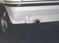
Intercoolers tend to blow up, specially under increased boost pressures. Special all-metallic parts are available, but to make the standard one harder, it can be strapped with one or two strong long plastic or metallic hose clips.
Procedure:You need to remove the intercooler or the front grille and loosen it. Just strap it in the vertical way with strong hose clips. It would be a good time to check the metal bits that keep the plastic ends (see arrows) in place, and maybe tighten them carefully with a hammer and/or some pliers. Notes:If you remove the intercooler, a black painting job would improve its heat radiation capability. |
 |
The Cup turbo actuation system is supposed to provide better response time. In addition, if you want to mount a bleed valve you need this system, because the double wastegate actuator hosing would compensate the bleeding.
This is the standard and the modified turbo actuator system:
 |
 |
How to do it easily:
After changing the hoses, you have to re-adjust the wastegate actuator length, or the turbo boost pressure will stay too low. You'll need at least three turns of the wastegate actuator (shortening the rod) to get the standard pressure again.
I suggest using new 1/4" fuel/emission hose so that you don't cut or modify the standard hoses. In addition you get new and reliable hose!
You can feel how, when half-closing the gas to reduce the speed, the turbo pressure doesn't decrease so fast, it continues spinning so that if you step again it takes less time to achieve the maximum turbine speed.

![]()
Adjusting the boost pressure via actuator
To adjust the boost pressure of our friend Garrett T2, simply bolt / unbolt the wategate actuator. The shorter it is, the more pressure it takes to open the wastegate, and therefore the more boost pressure you get (take care if you're increasing the boost pressure)
 |
Procedure:Remove or at least loose the thermical turbo screen to access and remove the circlip (a) that retains the turbo actuator rod (b) in the wastegate arm. Unbolt the nut (c) and remove the actuator rod from the wastegate. Use a pair of good plyers to hold the threaded zone (don't rotate it too much, not to damage the actuator internal membrane) and turn the rod. It's usually hammered to the thread, to prevent people from moving the setting, so drill the hammering point before turning it! Mount the circlip and test drive the car. Three turns clockwise should increase the boost in about 0.2 bar (3psi), but this is a matter of trial and error. When you finally get the desired boost pressure tighten the nut, mount the thermical screen again and that's it! Notes:Be careful with the wastegate actuator and rod not to bend it or damage it anyway as it can easily be ruined. |

![]()
Adjusting the boost pressure, Renault way
Using special equipment, Renault suggested adjusting the boost pressure this way to save the 'trial and error' part :-).
 |
Mount the following tools:
|
 |
|
Adjusting method:
You can mount a bleed valve to adjust the boost pressure on-the-fly. To make the leak at the turbo actuator work, you must go into the cup turbo actuator circuit. Otherwise the leak at one side of the wastegate actuator would compensate via the other side (take care if you're increasing the boost pressure)
|
The usual pneumatical system, a hose with a valve that can be located on the engine bay or the dashboard is not bad, but I tried an electropneumatical system. Electrovalves open and close some leaks and then allow different levels of boost. The mounting principle is the same. Procedure:In the cup turbo actuator circuit there's only one pressure hose that controls the wastegate. Insert as many T-pieces as leaks you plan, and use more hose to drive the air to the electro-valves. A convenient switch in the dashboard will let you open the valves by applying +12V to them. The valve outlet diameters must be calibrated to obtain the right leak. As an indication, using 1/4" hoses, valves with 3mm Ø would produce a leak that would increase in 0.15 bar (2.2 psi) the boost pressure. By the moment I'm using two Peugeot electrovalves. I get maximum boost pressures of 0.62 bar (9 psi) with all closed, 0.75 (11 psi) with one open and 0.9 (13 psi) with both open. And I've let space, wires, etc... for a third one! :-) |
 |
I have tried to take comparative performance figures (badly with a watch) in an unknown length of straight road. I started stopped and made a quiet 1st speed launch, then 2nd and 3rd with speed changes at 4500 rpm and then some meters in 4th gear. The differences are not very impressive, I should try to do it again in launched start to avoid differences due to clutch usage. Anyway the car is noticeably faster when you open the valves!
| Boost pressure | Times | Average time |
| 0.62 bar (9 psi) | 13.12 s. | 13.12 s. |
| 0.75 bar (11 psi) | 12.93 s., 12.34 s. | 12.69 s. |
| 0.90 bar (13 psi) | 12.98 s., 12.44 s., 12.32 s., 12.23 s. | 12.49 s. |
 |
It's common to use two or three identical valves. A multipole rotative switch can be arranged to open the valves in a daisy-chain fashion. The first position cuts the current to any valve. The second applies +12V (+) to the first valve (1). The third applies +12V to the second (2), and via a diode (anode to third position, cathode to second position) to the previous valve, and so on (The figure shows a three-valve circuit with a four position switch). Any bleed valve circuit must be done safely, a complete leak in the system would mean a completely closed wastegate and, if the boost safety switch doesn't cut, maximum boost pressure and a blown engine. |
![]()
Getting rid of the exhaust gases
The standard exhaust tailbox of the GT is not a very restrictive one (it contains rockwool instead of plate walls). In addition, in turbo engines that's not very important, because the turbo exhaust turbine is itself a bottleneck into the exhaust section. It's always good to improve, even in small quantities, but don't expect a great horsepower improvement with a tailbox!
| Buy an aftermarket performance exhaust tailbox. As the tailbox is prone
to rust and needs periodical replacing, there's plenty of market offer to
choose. I found a reduced-price Momo Corse tailbox with a 90 Ø round
exit. It looks cool, but the noise is very close to the standard one (and
many people choose their exhaust based on the noise. Vimesa, Devil, or
Remus give definitely nice sounds). Stainless steel systems and tailboxes
cost double the price of a standard one, but they should last more than
twice!
Performance tailboxes contain rockwool and they need to be rolled to let it settle and acquire its definitive noise, so they sound too low at the beginning. |
 |
The dismounting of the old tailbox is a difficult task and it requires time and patience not to ruin the exhaust pipe and create a leak forever. Keep in mind that the old tailbox won't be of any use anymore and cut its pipe carefully. Rotate it and help with a hammer on the tailbox (not the exhaust pipe that will remain in the car!)
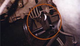 |
Have you noticed, even with your old standard tailbox, a noise when you find a bump in the road, the more when the more people are inside? That the typical tailbox elbow-rear axle crash. The standard rear support, letting a lot of weight on the exhaust pipe, is not enough. But most new tailboxes for the GTT have an additional support that would keep unused... so let's use it to fix the box too and avoid the disgusting noise! It's as easy as getting a bolt with round head and two nuts, drilling the plate that supports the rear brake limiter to fit it, use a rubber piece (the same as the old Renault 5 used for the rear exhaust support) and adjust the bold length to the ideal. I hope you get the idea, because my camera was unable to focus it better (sorry :-( ). |
The noise you get in the GT without tailbox at all is just nice (to my taste, of course), and it only might be a little disgusting when we talk about travelling more than 400 km. But if you are thinking in removing the tailbox, don't let the exhaust pipe as it is and buy or make a lateral or rear side pipe exit, because you can get some flames there and it's not far away from the fuel tank.
